Tuesday, July 7, 2015

High CMRR Instrumentation Amplifier (Schematic and Layout) design for biomedical applications

Instrumentation amplifiers are intended to be used whenever acquisition of a useful signal is difficult. IA’s must have extremely high input impedances because source impedances may be high and/or unbalanced. bias and offset currents are low and relatively stable so that the source impedance need not be constant. Balanced differential inputs are provided so that the signal source may be referenced to any reasonable level independent of the IA output load reference. Common mode rejection, a measure of input balance, is very high so that noise pickup and ground drops, characteristic of remote sensor applications, are minimized.Care is taken to provide high, well characterized stability of critical parameters under varying conditions, such as changing temperatures and supply voltages. Finally, all components that are critical to the performance of the IA are internal to the device. The precision of an IA is provided at the expense of flexibility. By committing to the one specific task of amplifying voltages, the IA manufacturer may optimize performance in this area. An IA is not intended to perform integration, differentiation, rectification, or any other non-voltage-gain function; although possible with an IA, these tasks are best left to operational amplifiers.

Recording the biomedical electronics is one of the challenges in a biomedical electronics detection system, because and low frequency, usually of few milli-volts or less and the frequency below 1 KHz. The biomedical electronics detecting system is shown in fig.1, which consists of electrodes, amplifier, LPF, sample and hold(S/H) and ADC.


 Meanwhile the recording electrodes might pick up many others unneeded inerferences or artifact signals. However, the biomedical electronics is too weak
to detect, therefore, we need a high gain , accurate, and high CMRR amplifier to reduce the common mode noise and to amplify the biomedical signal only. Then, the signal is passed through LPF. S/H and ADC to become a digital signal. After that, these digital data will be processed in PCs or microprocessors.

Designed Instrumentation amplifier specifications
 high CMRR = 127dB and
 gain = 58.5dB
 area = 65um x 65um
 power consumption = 1.02mW.

You can download Cadence files (Schematic and Layout) from here,

Schematic:
* 2-stage differential amplifier
* constant-gm bias
* Instrumentation Amplifier
* IA_test bench

Layout:

* 2-stage differential amplifier
* constant-gm bias
* Instrumentation Amplifier
* Extracted view of IA


Wednesday, December 3, 2014

Animatronic Arm / Hand Gesture control RF Robot

Abstract: In this project we are going to design an Animatronic Arm/Hand Gesture RF robot, It has two functions
1. RF based Animatronic Arm/Hand Gesture 
2. RF controlled mobile Robot

The system block diagram is shown in the below figure. It contains
a). Flex Sensors 
b). Opamps
c). ATmega16-A board
d). 433MHz RF transceiver s
e). 8052 controller
f). DC Motors and servo motors
g). HT12D and HT12E 
h). Motor driver L293D

Working of Mobile Robot: 
At the transmission section we have HT12E with 4 push buttons and a 433MHz transmitter as shown in fig.1, 4 buttons are used for forward,backward, left and right controls.

At the receiver section RF receiver will receive the transmitted data and HT12D decodes the received data and sends 4-data bits to the motor driver L293D as shown in fig.2.

Block Diagram
Fig.1 Transmitter Circuit for Robot Movement
Fig.2 Receiver Circuit for DC motor Controlling
Working of Animatronic Arm:
Flex sensors are a kind of variable resistors, who's resistance varies with flexing. This application is used in animatronic arm. The basic circuit of flex sensor is shown in the below circuit, it is connected as a potential divider circuit and the output is connected to a buffer. The voltage variation can be calculated by 'Vout' equation.


Here we used two flex sensors for two fingers. Output of the buffers are given to the analog pins of ATmega16-A board. Inside the controller analog data is converted to digital form and based on the two output values 4-bit data is sent to the I/O ports. 4-bit output is then given to the HT12E encoder and it transmits the data as shown in fig.3 and 4

Fig.3 Flex Sensor circuit

Fig.4 ATmega16-A circuit for data processing
At the receiver side the received is then decoded and given to the 8052 controller. The code is written such that the animatronic arm imitates your fingers based on the flex sensor voltage values.  The pulse width of the servo motors is changed according to the received data. The total pulse width is 20ms. for a 1 ms ON time it will be at 0 degrees and for 1.5 ms ON time shaft position will be at 90 degrees and for 2 ms ON time at 180 degrees as shown in the below fig.5 and 6

Fig.5  Receiver Circuit interfaced with 8051
Fig.6 servo motor interface with 8051
Working Video:

Resources:

1. ATmega16-A Transmitter CODE Download the code here
2. 8052 Receiver CODE Download the code here

NOTE: 
1. Since we used two pairs of RF transceivers we used different address at HT12D/E
2. We have designed it for only two fingers and a basic movement.
    For 5 fingers and much more degree of freedom use 5 flex sensors and Zigbee module 

Sunday, November 23, 2014

GSM Interfacing with Arduino Uno board/ Temperature monitoring using LM35

Abstract: In this project we are going to develop a system, which will monitor temperature in the surroundings and sends a message to the corresponding person. We used GSM SIM300 Modem, Arduino Uno board and LM35 sensor. This system can be installed in Forests, Industries and even in homes to monitor the fire accidents and intimates the person to take immediate action.

Figure below shows the circuit connections.

LM35 is a temperature sensor,who's output varies according to the temperature variations. Every 1 degree C temperature variation changes its output voltage by 10mv. If the current room temperature is 25 degree C then the output voltage will be 0.30 volts. Vcc of LM35 is connected to 5v supply of Arduino Uno , Analog output and GND pin to A0 pin ,GND of Arduino pin respectively.

GSM interfacing to Arduino Uno board:

Connect Receiver pin of GSM modem to the Transmitter pin of Arduino Uno, Transmitter pin of GSM modem to Receiver pin of Arduino Uno and connect both the grounds. Insert SIM and plug the modem. Wait for the GSM modem to get network, indicated by LED blinking. 

Flow chart: 


Resources:

1.  to download the Arduino Uno Code
2.  to see LM35 datasheet

Friday, November 7, 2014

DHT11 Interfacing with MATLAB and Arduino

Abstract: In this project we are going to interface digital Humidity and temperature sensor (DHT11) with Arduino Uno board and with MATLAB. we are going to display the temperature and Humidity data, received from DHT11, in LCD screen and also plotting them in MATLAB simultaneously.

From the datasheet it mentioned that DHT11 outputs 40bits of data. It contains 8-bits integral RH data+ 8-bits Decimal RH data+8-bits Integral Temperature data+8-bits decimal Temperature data+8-bits check sum. Read datasheet[3] for more details. The library for DHT11 sensor is available in the resources. Add the library[4] in this path "C:\Program Files (x86)\Arduino\libraries\DHT11" (In my case). 

Connect DHT11 sensor to the Arduino Uno board as shown in the below figure and also plug your Arduino board to PC/Laptop.
Now open Arduino IDE tool and run DHT11_Arduino_code[1] and upload it on to the board.
Open MATLAB and run the DHT11_MATLAB_code[2].  
                                      
                                                         Working Video
Resources:


Temperature Monitoring using Arduino Uno

In this project we are going to monitor room Temperature with Arduino Uno board. Connect the temperature sensor LM35 as shown in the figure. Output of the LM35 is connected to the Analog port A0, itreads the temperature variation and it displays the digital data on to the LCD screen. Run the code given below.

#include <LiquidCrystal.h>

// initialize the library with the numbers of the interface pins
LiquidCrystal lcd(12, 11, 5, 4, 3, 2);

void setup() {
  // set up the LCD's number of columns and rows:
  lcd.begin(16, 2);
  // Print a message to the LCD.
  lcd.print("Temp monitoring");
}

void loop() {
  float temp;
  temp=analogRead(0);
  lcd.setCursor(0, 1);
  lcd.print("Temperature=");
  lcd.print(temp);
  delay(100);
}

Sunday, November 2, 2014

Interfacing Arduino Uno with MATLAB

Method-1:
Step-1: Download the ArduinoIO MATLAB support file from here 
Step-2: Download the Source file from here 


Step-3: Add the downloaded ArduinoIO folder to your MATLAB bin path 
in my case it is "C:\Program Files\MATLAB\R2012a\bin"

Step-4: Connect your Arduino board to your PC/Laptop

Step-5: Open Arduino IDE Tool and copy the downloaded source file on to the new sketch file. Compile it and upload it on to the Arduino Uno board.

Step-6: Now Open your MATLAB and type "arduino" on command prompt. You will see some scrolling message. Then type "a=arduino('COMx'), x is your COM port number which is assigned to your board. 

Step-7: If you want to read analog port data then type "b=a.analogRead(0)" this will read analog port A0 data. If you want read/write any digital pin use these instructions
 a.pinMode(9,'input'); 


 a.pinMode(13,'output');

 a.digitalwrite(13,0) ;


arduino;
a=arduino('COM3'); // In my case it is connected to COM3 port
t=1:1:100;
b=a.analogRead(0);
plot(b);
a.pinMode(8,'input');
a.digitalRead(8);
a.pinMode(13,'output');
a.digitalWrite(13,1);
pause(1)
a.digitalWrite(13,0);

Method-2:

Step-1: Write this code in Arduino IDE tool and upload this code on to your board. 
void setup()
{
   Serial.begin(9600);
  while (!Serial) {
      ; // wait for serial port to connect. Needed for Leonardo only
    }
}

void loop()
{
  Serial.print("Hello World!");
 // Write your code here
}

Step-2: Open MATLAB and type this code in matlab file and run the code

s = serial('COM3'); // In my case it is connected to COM3 port
fopen(s);
fprintf(s, 'Your serial data goes here');
out = fscanf(s);
% Data Analysis 
fclose(s);
delete(s);
clear s;


ATmega16A/32 USB Boot-loader Circuit/Programmer

Fig.1 shows the ATmega16A USB boot-loader circuit. Integrate all the components shown in the circuit. Download the AVR USB Flash programmer tool and upload your .HEX file on to the microcontroller. The circuit can be used as a separate programmer or it can be integrated on to your project.


Fig.1 ATmega16A USB Boot-loader circuit

 Fig.2 shows the ATmega16A/32 USB boot-loader and Development kit. Connect all the components and upload your .HEX file on to the controller. This circuit can be used to program your controllers and also can be used as a standard development board. It has character LCD and SPI connections. This circuit is best for students doing embedded system projects on ATmega16A controller.
Fig.2 ATmega16A/32 USB Boot-loader and Development kit circuit

Saturday, June 21, 2014

PWM based temperature controller using ATmega16A

Abstract: In this project we are going to design an embedded system that controls the temperature using a PWM signal, generated by a ATmega16A controller. 

Here we assume that our required temperature is 145 degrees C' and the bandwidth is ∆T= 20 degrees C. And also assume that it takes 10sec to heat up to 145 degrees C(this is not true in all cases). With  ∆T= 20 degrees C maximum temperature is 155 degrees C and minimum temperature would be 145 degrees C. Duty cycle can be calculated using the following formula..
                T_duty =1- (T_sensor – T0)/∆T
                   here T0=145 degrees C and T_sensor is the temperature sensor output
If you want to control higher temperatures, say above 150 degree C, then you have to use Thermistors instead of LM35. Here 10*T_duty gives the ON time duration and 10*(1-T_duty) gives the OFF time duration.

Operation:- The temperature sensor will sense the temperature of the device/chamber and a Nichrome wire used as a Heating element. Here LM35 is connected to the internal ADC0 pin of ATmega16A controller. ADC output will be the T_sensor value and is used to calculate the T_duty cycle period. PD0 pin carries the PWM signal, is connected to the Nichrome wire. If there is a change in temperature T_duty will change and the PWM will change. Example, if the temperature is higher than the required then the T_duty (ON time) will be reduced and OFF time will be increased to cool down the temperature. If the temperature is lower than the required then the T_duty (ON time) will be increased and OFF time will be reduced to increase the temperature.   
When the temperature is 144 degrees C 
       T_duty = 1-(144 - 135)/20 = 0.55*10=5.5sec = ON time
       1-T_duty = 1-0.55= 10*0.45=4.5sec = OFF time
 When the temperature is 150 degrees C 
       T_duty = 1-(150 - 135)/20 = 0.2*10=2.5sec = ON time
       1-T_duty = 1-0.25= 10*0.7=7.5sec = OFF time

Flow chart:-   to download the source code

NOTE: The time required to heat up to a required temperature will depend on the type of heating material used. Calculate the time required and use it to generate PWM. 


Saturday, June 14, 2014

Wheatstone bridge application using ATmega16A

Abstract: In this project we are going to build a circuit that calculates the unknown resistance in a Wheatstone bridge using voltage subtractor and Internal ADC of a ATmega16A.

Wheatstone bridge is used to calculate the unknown resistance in a circuit. Here we are using OpAmp based subtractor circuit to calculate the voltage 'Vg', which is used to calculate the unknown resistance. The two buffer amplifiers are used to provide virtual isolation between the wheatstone bridge and the subtractor. Below circuit shows the working of a subtractor,


NOTE: In case of ATmega16A we don't need to use external subtractor because ATmega16A is having differential input mode.

Here we selected external ADC reference voltage 5V. So, the output of a ADC value is multiplied with its resolution to get input voltage, 5/1024. This voltage is given as 'Vg' in wheatstone bridge equation to calculate the resistance, remaining three resistors are set to 1k ohm.

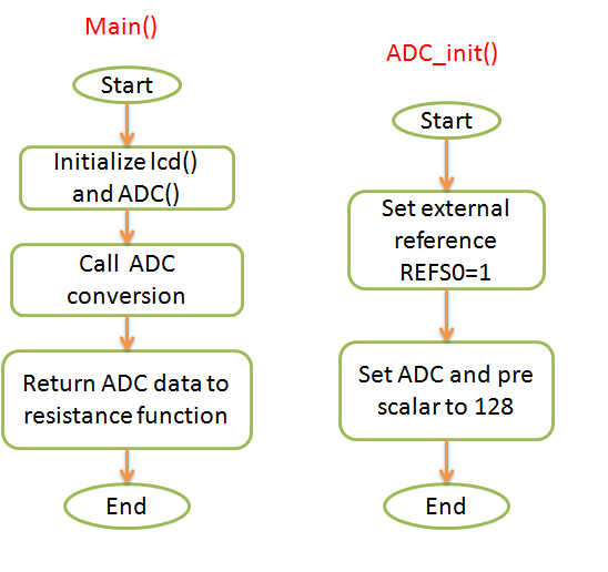
Here's the program flow


  to download the code

Working images of the total circuit


Click here to see the working video.


Saturday, March 15, 2014

How to Embed/Integrate the Circuit?

This is for those who doesn't know how to solder/integrate/Embed their circuits/system on to the Veroboard/PCB/Vector board. Many new people do the same mistake 

- first they will solder every thing and they inserts all ICs in it, after that once they switch on the power supply   they will experience short circuit, higher voltage, low voltage and IC burning problems. 

- These problems are due the lack of knowledge in design.

- Follow these steps to avoid such kind of problems 

1. Be ready with your working circuit, components, digital multimeter, soldering iron, etc.,

2. In any circuit first solder the power supply, it may be from AC to DC or DC to DC.

3. Check the input, output and intermediate voltages(in case of many stages) with Digital Multimeter(DMM).
    Verify the measured voltages with required voltages. If not, verify the connections and see whether you         connected the same component or not. If you get the required voltages then proceed to the next step,           otherwise don't proceed until you rectify the issue because this will cause to major problems further.


4. Now First solder the IC bases and give only Power supply connections to the base. Check the voltage in each and every pin with respect to the ground pin. If you get the required voltages proceed to the next step,   otherwise verify the connections.Make sure that ICs are not inserted in to the bases.


5. Connect the other components like resistor, capacitor networks and relays etc., check the input and output of each sub network individually. If you get the satisfied voltages then integrate them together. Check for the entire circuit voltages at each pin with respect to the ground pin. Check for the connection if you get undesired results. Make sure that ICs are not inserted in to the bases.


6. If you are sure that you are getting all desired voltages you can insert ICs in it. Check the connectivity of each pin with multimeter to identify whether there is any loose contact or short circuit contact.


If all the connections and input output voltages are correct but still if the functionality is wrong then make sure that IC is working properly or not and check for the programming errors.


Monday, July 22, 2013

GSM based Anti Theft security locker system

Generally in our homes and banks we will put our money ,Gold and other expensive items in the lockers. In case if there is no person in the home/bank, there is a chance that an unauthorized person (stealer) may broke the locker and steal your property. There is no guarantee that you will get back your property. Keeping this point in mind i designed a security system which will alert the owner and Cops when unauthorized person opens your locker. 
Block diagram:                                                                                                


Working:
When the locker is closed the controller will not send any message to the owner. When unauthorized person opens the door the controller will send a message "Warning: Unauthorized person opened the lock" to the owner ( and also to the police controller room with address if required).
Schematic Diagram:
unauthorized person opened the lock

to download C-code
 Flow Chart: