Abstract: In this project we are going to design an embedded system that controls the temperature using a PWM signal, generated by a ATmega16A controller.
Here we assume that our required temperature is 145 degrees C' and the bandwidth is ∆T= 20 degrees C. And also assume that it takes 10sec to heat up to 145 degrees C(this is not true in all cases). With ∆T= 20 degrees C maximum temperature is 155 degrees C and minimum temperature would be 145 degrees C. Duty cycle can be calculated using the following formula..
T_duty =1- (T_sensor – T0)/∆T
here T0=145 degrees C and T_sensor is the temperature sensor output
If you want to control higher temperatures, say above 150 degree C, then you have to use Thermistors instead of LM35. Here 10*T_duty gives the ON time duration and 10*(1-T_duty) gives the OFF time duration.

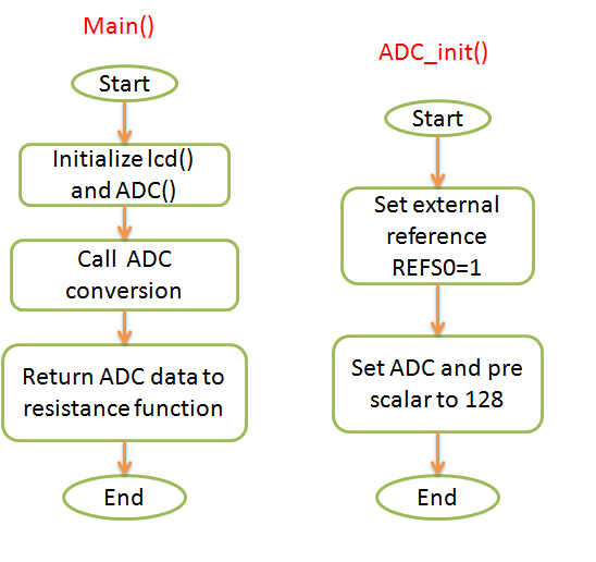
Operation:- The temperature sensor will sense the temperature of the device/chamber and a Nichrome wire used as a Heating element. Here LM35 is connected to the internal ADC0 pin of ATmega16A controller. ADC output will be the T_sensor value and is used to calculate the T_duty cycle period. PD0 pin carries the PWM signal, is connected to the Nichrome wire. If there is a change in temperature T_duty will change and the PWM will change. Example, if the temperature is higher than the required then the T_duty (ON time) will be reduced and OFF time will be increased to cool down the temperature. If the temperature is lower than the required then the T_duty (ON time) will be increased and OFF time will be reduced to increase the temperature.
When the temperature is 144 degrees C
T_duty = 1-(144 - 135)/20 = 0.55*10=5.5sec = ON time
1-T_duty = 1-0.55= 10*0.45=4.5sec = OFF time

T_duty = 1-(150 - 135)/20 = 0.2*10=2.5sec = ON time
1-T_duty = 1-0.25= 10*0.7=7.5sec = OFF time


NOTE: The time required to heat up to a required temperature will depend on the type of heating material used. Calculate the time required and use it to generate PWM.